For any comments or queries regarding this page
Please contact David N Williams on pondside@talktalk.net
The Southend Waterworks Company (SWC)
Southend, as elsewhere, obtained its water from springs, shallow wells, and ponds, until the Railway arrived in 1856, causing an increase in population and big increase in visitors. From 1865 deep wells and boreholes were dug into the sands and chalk below the London Clay. These were used until 1984. From 1927 until the present time, treated river supplies were made essential due to inadequate chalk supplies.
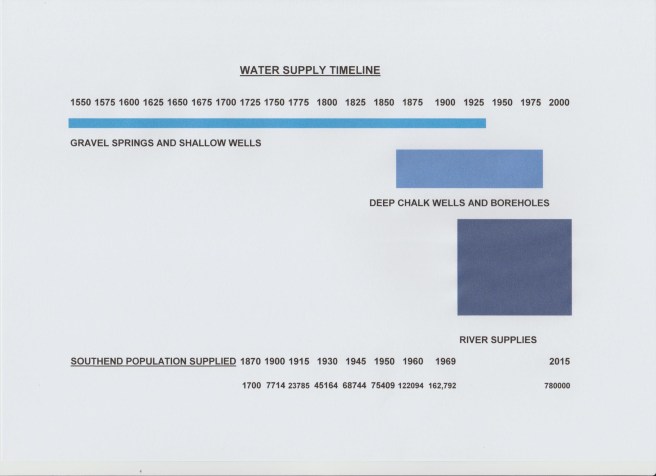
Water Supply Timeline indicating periods of types of source (DNW)
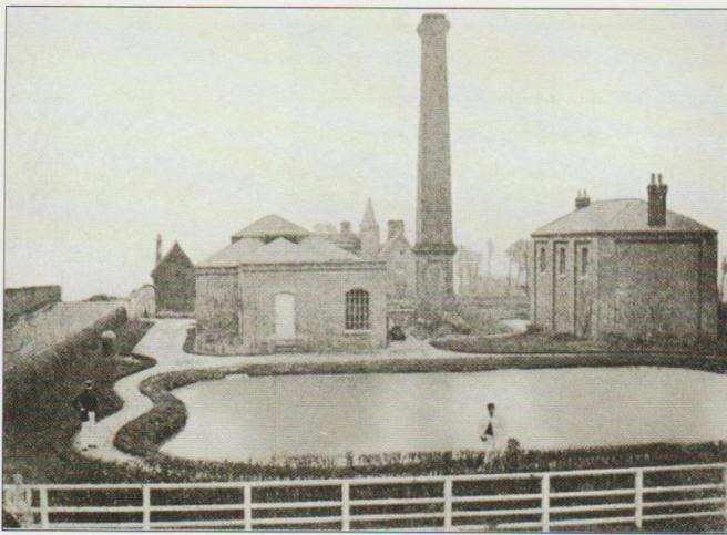
Southend No 1 Well Pumping Station 1865
The Southend Waterworks Company was founded by Thomas Brassey as a private undertaking in 1865, primarily to supply water for the steam powered locomotives, with which he had been involved. It became a Limited Company upon his death in 1871, and was incorporated in 1879.
He constructed in Southend the first deep borehole in Milton Road, ( Well No 1) which was first pumped in 1865. This had been dug 6ft in diameter and lined with brickwork for 385 ft, then bored 9ins to 2.5 ins to 906 ft. There was an associated storage reservoir, 300,000 galls and a later tower, of 50,000 galls constructed nearby in Cambridge Road, Southend, see below. This was followed by two storage reservoirs at Vange, of 8.0 million gallons capacity, and two at Thundersley holding 3 million gallons. The storage reservoirs provided water at peak times, when consumption, exceeded the flow from the boreholes. A treatment plant was built at Vange for the combined treatment of 5 boreholes, three at Vange and two at Fobbing. Lime /Soda softening was required to reduce the hardness of the combined water. This also had a lime recovery plant, the first of its kind.
The water from most of the Wells was obtained using a steam powered lift pump to lift the water to the enlarged part of the well and a ram pump to pump it into the water main.
This was soon followed by a network of boreholes and distribution mains, until in 1921 some 39 had been sunk.

Southend Sea Front with Water Tower top right

Southend Water Company’s First Water Tower

Scratton Road Tower from previous picture
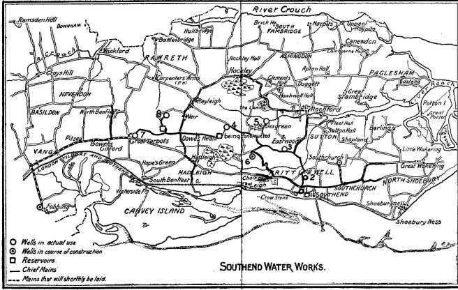
Wells sunk by 1901
Southend Boreholes * Those still in use in 1966, Numerous boreholes were discontinued after the introduction of the major supply from Hanningfield Treatment works was introduced approx 1956.
Name Depth in ft First Pumped
No 1 Southend 906ft 1864
No 2 Prittlewell* 877ft 1881
No 3 Eastwood 871ft 1890
No 4 Oakwood* 868 1894
No 5 Nobles Green* 859 1895
No 6 Picketts 801 1900
No 7 Thundersley 670 1899
No 8 Burches 854 1899
No 9 Southchurch 771 1901
No 10 Fobbing Main 756 1902
No 11 Vange Main 330 1904
No 12 Fobbing Aux 1153 ft 1904
No 13 Vange Aux 257 1905
No 14 Pitsea 268
No 15 Bowers Gifford 317 1906
No 16 Grt Wakering 618
No 17 Nevendon 452 1907
No 18 Leigh 600 ft 1896
No 19 Slices Gate 900 1904
No 20 Downham* 701 ft 1908
No 21 Slices Gate (Main Well) 400 1910
No 22 Wickford* 598ft 1911
No 23 Vange West 398 1911
No 25 Wakering Wick* 446ft 1912
No 26 Benfleet 642 1900
No 27 Ramsden Heath 514ft 1914
No 32 Mountnessing* 485 1921 Barling* Leighbeck Holehaven No 1 459 1892 Holehaven No 2 492 1909 South Fambridge 313 Ft 1906 Shoeburyness No 1 1048 Ft 1887 Shoeburyness No 2 517 ft
In 1947 seven of these were converted to electric pumping, and in regular use, the remainder were only used for periods of peak demand, and were all converted by 1955.
To view section diagram of Leigh Well, please click on above.
Whilst searching for the location of Leigh well, I came across a Lapwater Farm and an associated story from a New Zealand paper of 1893, entitled ” The Legend of Lapwater Hall”
The Vange and Fobbing wells were a major source in the early 1920’s, and a lime/soda softening plant was built to soften Vange West, Fobbing and Fobbing Tunnel which were all hard, and blend them with Vange and Vange Main which were both soft. The Fobbing wells also having a high iron content. There was also a lime recovery plant, the first of its kind, and two treated water reservoirs of 8 million gallons capacity each.
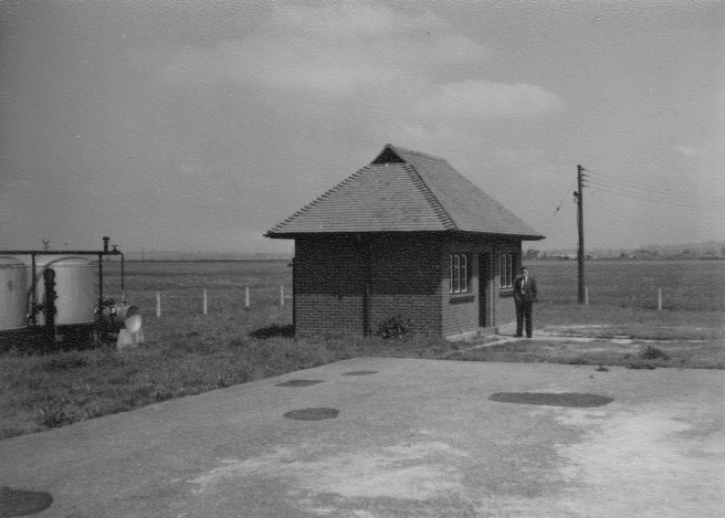
Borehole pumping station after electrification
When the Langford river source came on stream in 1927, the Fobbing wells and Treatment plant were abandoned and the two Vange wells kept for periods of high demand.
In 1962 with a growing demand for water, the Vange and Fobbing Wells were test pumped for two months during 1963 and a decision taken to build a new softening plant which began operating in May 1966, and cost approx £176,000. The previous treated water reservoirs becoming the raw water storage, and a new treated water reservoir constructed. This was designed to be a semi automatic unmanned plant. The wells and Treatment plant were abandoned for a second time in 1984.
 Vange Reservoir
The Chemical analysis of most deep wells and boreholes remained very constant whilst being regularly pumped. The exception were a few which suffered from sea water intrusion, as on Canvey Island, where Holehaven No 1 was pumped continually to waste to prevent sea water affecting Holehaven No 2, on the same site. One of these was later affected by gas escaping from an adjacent underground gas storage reservoir. There was a problem with a few wells into which sand penetrated. In later days a surface filter was used to remove the sand prior to distribution. An early filter employed at Shoeburyness was of horse hair, inserted between 381 and 517 feet down the well.
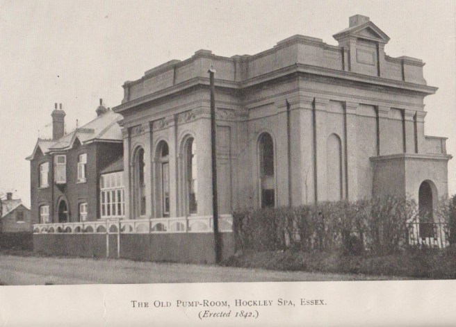
Mineral and Medicinal Springs and Wells
Some wells and Springs were claimed to have special properties and became famous with people flocking to bathe in, or drink the water, such as Hockley Spa in Essex. People travelled great distances until the fad wore off, and they became disused. The Spa at Bath however, remains popular today.
From 1856 until 1960 the SWC either bought or became responsible for other municipal undertakings, with an area of supply, between the Rivers Crouch and Thames. reaching from Foulness Island in the East to Langdon Hills and Thurrock in the west, an area of 160 sq miles.
By 1920, the limit had almost been reached of water extracted from the chalk, sufficient for the growing population, caused by the Industrial Revolution . The slow flow of water through the fissures in the chalk, limited the amount of water extracted from the boreholes. Continuous pumping lowered the level of water in the chalk, affecting adjacent boreholes unless more than a mile and a half apart leading to intermittent pumping at some sites. An alternative sustainable source had to be established. Despite being adjacent to the sea, desalination of salt water to water suitable for consumption is very expensive, with a high amount of energy required. From 1927 the boreholes were used as an auxiliary source predominantly in summer when demand was too high for the river sources. They were pumped once a year for the steam boilers to be inspected and tested. Their use was discontinued in the 1980’s when the European Directive for Drinking water advised that high sodium waters could be a health hazard.The Mountnessing borehole’s area of supply was initially unique in that it was not connected to any other supply source
River Abstraction See (Langford Treatment Plant)(Rivers Chelmer and Blackwater)
In 1921 a joint application was made with the South Essex Water Company, for water to be extracted from the River Stour at Langham, in Essex.
The failure of that application resulted in the Southend Waterworks Act of 1924 passed in Parliament, granting the Southend Waterworks Company the right to abstract water from the rivers Blackwater, Chelmer and Ter, at Langford for public consumption.
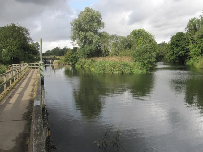
Both the Rivers Blackwater and Chelmer had feeds from the gravel beds, either though the river bed or via adjacent springs, and run off from mainly agricultural land after rainfall. This was described in a paper by Dr G U Houghton illustrating the loss and recharge from the gravels below the River Stour.
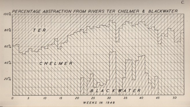
River Abstraction at Langford during 1948
Currently water from the River Chelmer, is only abstracted at Langford, and supplies a population of approx 429,400 from Langford and Hanningfield. This totals 780,700 with abstraction from the River Blackwater There is no longer abstraction at Sandford Mill, Chelmsford being supplied by from the South Essex works at Langham and Layer. Compensation water is metered into the Chelmer and Blackwater Canal, to maintain the level to Heybridge sea lock.
There was also included in the Southend Waterworks Act, a requirement to soften the water, to a total hardness of 150 mg/lt as CaCO3, as the boreholes supplied very soft water, and that from the rivers was hard, containing high levels of Calcium.
A similar act had been passed for Chelmsford Borough Council to abstract from the river Chelmer in 1922. These were the only two water treatment works in the England to employ simultaneous softening and purification.

The Original Oakwood Reservoir before curved metal roof replaced by flat concrete
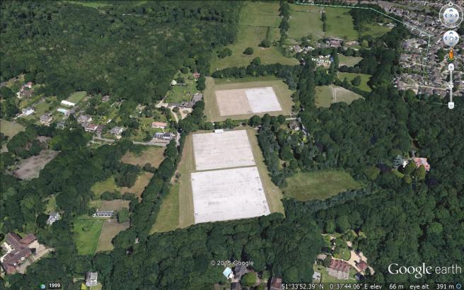
The Current Oakwood Reservoir Complex
A 28 inch main was laid from Langford to Belfairs wood on the outskirts of Southend where the Oakwood storage reservoir was constructed. Later a 32 inch main was laid alongside when the pumping capacity was increased at Langford from 8 to 12 mgd. A Reservoir was also built at Bushey Hill to reduce the pumping head, and booster pumping station at Hullbridge using the electric pumps originally used at Langford installed in 1963.
Oakwood was the main storage reservoir supplying treated water to Southend by gravity.Trunk mains were then laid to connect the reservoir to the borehole distribution network. In subsequent years additional storage reservoirs were added at Oakwood, increasing the capacity to 17 million gallons, plus at Benfleet, Rayleigh and Prittlewell.
It was a condition of his employment, that the Chief Engineer of the Company resided next to Oakwood Reservoir so was one of the first to be supplied, and therefore could give an early warning of potential problems.
By the late 1940’s , with an ever growing population and supply problems in the summer drought period, the Hanningfield Scheme was designed. (See Pages 21 and 30) This abstracted surplus river water at Langford, mainly in the winter periods, and stored it in a large land based Reservoir at South Hanningfield. Water was required to be softened as at Langford, but the output was shared between the Southend and South Essex Waterworks Companies. This came on stream in 1956.

A Southend Waterworks Advert 1955
The Essex Water Company was formed from the Water Orders of 1970 and !971 combining the Southend Waterworks Company, the South Essex Waterworks Company, and the Water undertakings of Chelmsford, Maldon and Witham. (See Pages 4 )
The Essex and Suffolk Water Company was formed by the merger of the individual Essex and Suffolk Water Companies (See Page 41)
