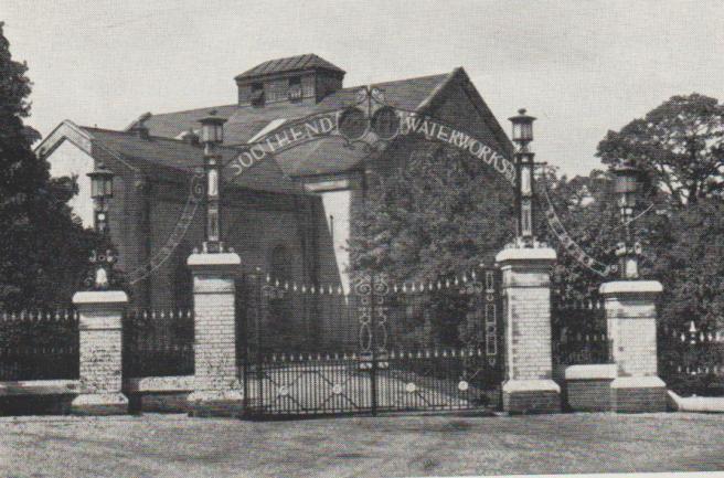
Langford Pumping Station
Langford near Maldon in Essex, was a nondescript village, consisting of a sparse ribbon of houses along the road between Heybridge and Hatfield Peverel, together with a few isolated houses and farmhouses, until the Southend Waterworks Company arrived in 1925. It did however lie adjacent to the confluence of the Rivers Blackwater and Chelmer at Beeleigh, prior to discharge into the tidal River Blackwater, which made the location eminently suitable as a reliable source of fresh water. A recent Archeological dig, adjacent to the Chelmer, upstream of Langford, has uncovered Saxon remains from 5000 BC including the oldest cremated human bones found in the UK. Prior to the canal and weirs being built the high tide would have reached further up the shallow river. The village lies in the the Blackwater estuary catchment area containing the rivers Blackwater and Chelmer valleys, on a gravel layer some 12 feet thick, which originally provided two public and some private wells. Below which was a layer of clay a few hundred feet thick. Some isolated houses relied upon ditch water.
Langford Pumping Station
The Langford Water Treatment works of the Southend Waterworks Company, commenced operation in August 1927. The advent of the Southend Water Company at Langford brought employment and a significant increase in population to the village, where 16 houses were built and a few purchased for the workers. Mill House was purchased to supply accommodation for the Resident Engineer and Chief Chemist. Also Mill Cottage below which had been part of a larger building and at one time the village Public House.
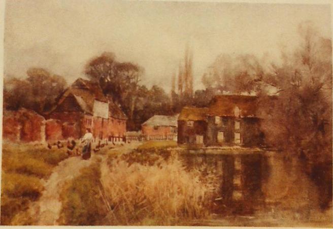
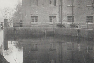
Mill Cottage Langford
Mill Cottage, which still exists,was part of the building on the left, the mill building on the right at the head of Langford Cut, no longer exists, having burnt down in 1879. The small building centre background is now the Village hall. Mill cottage housed DNW when first married.
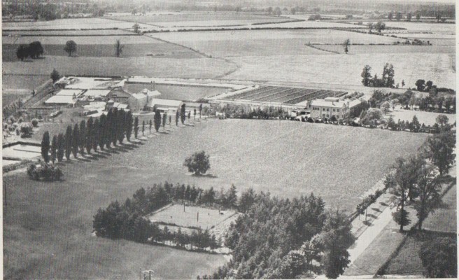
The Company also were involved in community events such as hosting the annual village fete , on the lawn in front of the Treatment Plant, providing a cricket pitch, and tennis courts adjacent to the now Village Hall. A few salmon used to appear annually, and still do, on their way upstream. The Chief Engineer in the 1960’s had the salmon caught using the nets from the tennis courts. A local angler has rebuilt in 2015, the salmon ladder at the Langford River Blackwater weir pool, that was originally installed in the 1970’s to assist the salmon to reach the gravel shallows upstream. Prior to 1797, the River Chelmer being canalised ( see http://www.chelmercanaltrust.co.uk for detailed history) there would have been numerous shallow gravel stretches, between Maldon and Chelmsford suitable for Salmon Spawning. There was also a preponderance of elvers that appeared in March/April.

Small weirs created to assist eels upstream
Water from the combined inlet of the Rivers Chelmer and Ter, flowed by gravity along a 33 inch main from Rushes lock 2.5 miles into the two Langford sedimentation reservoirs, which held a total of 60 million gallons, and had a depth of 22 ft 6 ins when full. These also served as emergency storage in the event of River pollution preventing abstraction from one or other of the Rivers. Water was also pumped into the reservoirs from the River Blackwater, by electric pumps installed in the old Langford Mill. Initially water was taken preferentially from the Chelmer and Ter to avoid the cost of having to pump the Blackwater into storage. In summer the water in these reservoirs were prone to algal blooms. There were times when short circuiting occured and the incoming water flowed directly to the outlet, instead of mixing in the Reservoir. A research project was carried out using a short life radioactive tracer to determine the extent and found that water could be leaving the reservoir just 30 mins after entering.
Water having gravitated from the sedimentation reservoirs to the pumping station, was pumped to the treatment works by the two of the three steam driven vertical triple expansion rotative pumping engines. Each engine had a capacity of 4.4 million gallons per day, and were made by the Lilleshall Company. The engines were worked in pairs to provide a maximum 8.0 m.g.d. Only one of the engines remains in the steam pumping station, now called the Museum of Power. Steam was provided by three high pressure boilers, One large and two small , working at 210lbs/sq inch at 150 F . draught was provided by a chimney 150 ft tall. These were fuelled on a mechanical grate, by small pieces of coal approx half an inch in diameter. This originally was transported to Langford by train using the Witham to Maldon branch line, then collected by tractor and trailer. Laterly, the coal then arrived by lorry direct to the works. Regular analysis had to be made of the water content of the coal to ensure the suppliers were not soaking the coal prior to delivery.
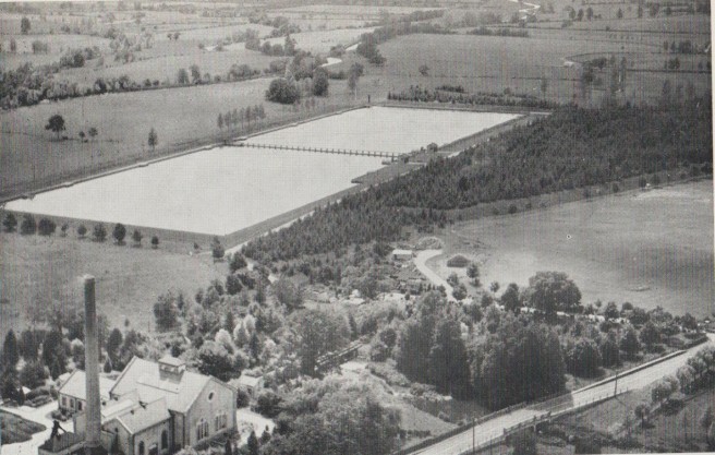
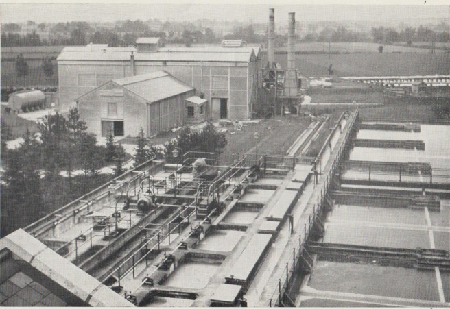
Langford Sedimentation Reservoirs with Pumping Station in foreground
Electrical Power for the Pumping Station, Treatment works and Blackwater abstraction pumps was provided by three 80KW steam driven 480 volt DC generators.
A small amount of river water is allowed down the canal to maintain the level to Heybridge Basin, allowing boats to lock in and out.
Water flowed though the treatment plant and then gravitated back to the steam driven pumps via a small balancing reservoir. The steam pumps had two sets of pistons driven by the same shaft, the short low lift for pumping up some 30 ft from the sedimentation reservoir to the treatment plant and the longer high lift for pumping the water to Southend, against a head varying from 240 to 300 ft head Two steam engines were used together, with one remaining on standby.
The water pumped though a 28 inch main 14 miles to Oakwood service Reservoir on the outskirts of Southend. The main crossed the River Crouch in a tunnel of approx 8ft diameter, 552 feet long, some 32 feet below the river bed.

Combined Rivers Chelmer and Ter Intake at Rushes Lock
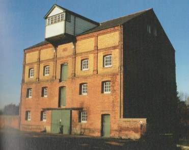
Langford Mill, Housing the Blackwater Abstraction Pumps at the rear.
Abstraction point at Rear of Langford Mill

Sedimentation reservoir Inlet, initially gravity fed from Chelmer and pumped from Blackwater
In 1953 with the construction of Hanningfield Reservoir and the associated No 1 pumping station at Langford, a combined abstraction point was built on the River Chelmer opposite the works. Also a new intake was built on the River Blackwater, upstream of the Mill pumps, and control weirs. Six pumps with a max capacity of 35 mgd pumped river water through a 48 inch main to Hanningfield reservoir. With two pumps, of max capacity 17 mgd to supply the Langford raw water reservoir.
1953 Hanningfield No 1 Station pumping Station at Langford.
Pumped both Blackwater and Chelmer water to both Langford and Hanningfield Reservoirs.
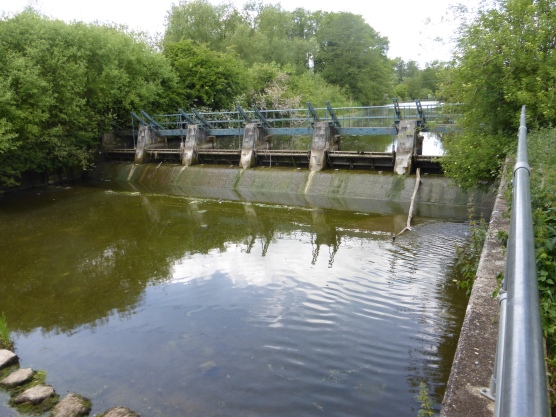
Automatic Tilting Weirs
These were installed below the Intake on the Chelmer to regulate the height of the River/Canal . These were operated by the weight of the water. A small volume of water bypasses the weirs to the right, to prevent stagnation and fish deaths. Prior to the installation of the tilting weirs the canal was at normal level down to Beeleigh Falls House and remains of Beeleigh Mill. An old school friend lived at Beeleigh Falls house during this period, and they used this stretch as their swimming pool, often having skinny dipping sessions, after parties which his parents organised.
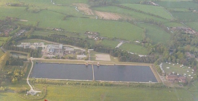
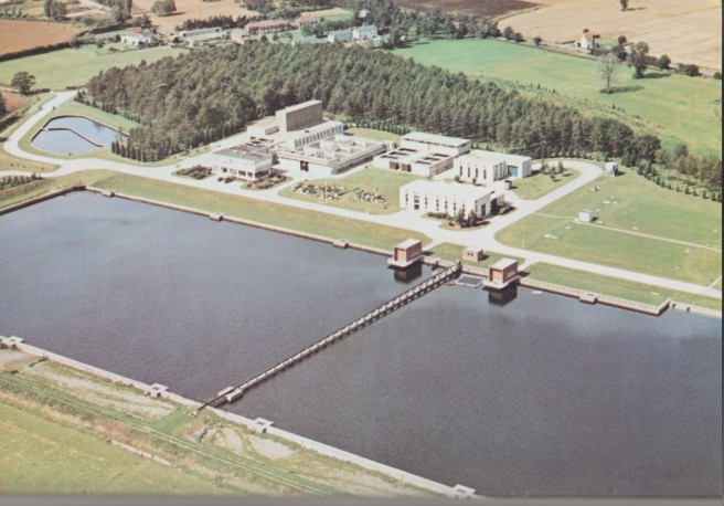
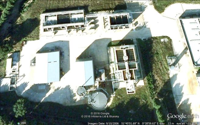
Langford Treatment works with No 1 Pumping station on right and Sewage Recycling Plant on the left (DNW Photo taken whilst flying light aircraft)
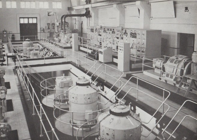
In the early 1960’s demand was rising and the steam pumps were replaced with electric pumps in August 1963, each capable of pumping 6 million galls per day. This eliminated the need for boilers and the 150 ft tall chimney to the boiler house was demolished. This was called No 5 Pumping Station and was built onto the Hanningfield No 1 Station.
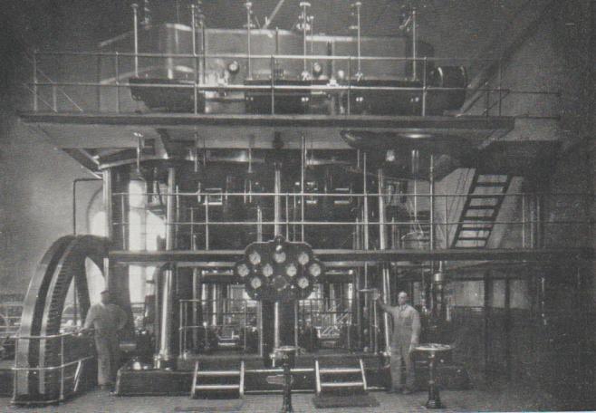
Triple Expansion Steam pumps
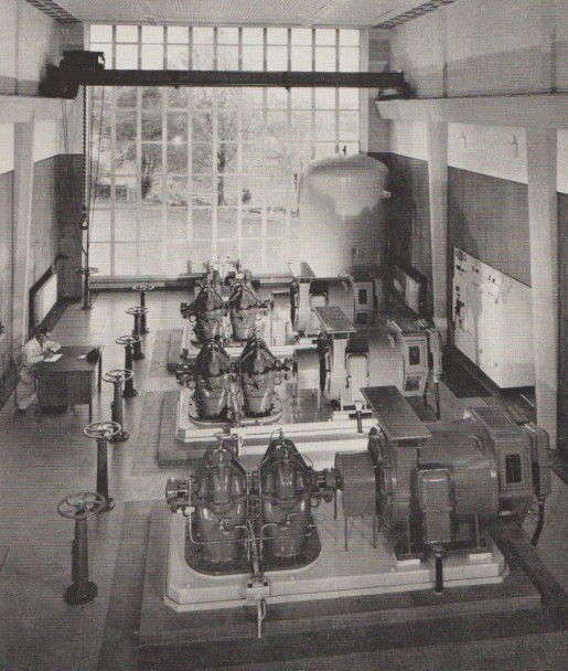
Electric Pumps Installed 1963
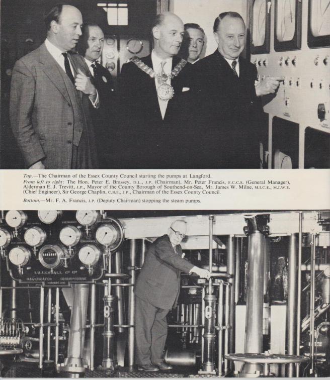
The Official opening of the Electric Pumping Station and Turning off the Steam Pumps
Proposed Maldon Reservoir
In 1964 a proposal was made to construct a large river water storage reservoir on the outskirts of Maldon, in the valley between Maldon and Mundon.

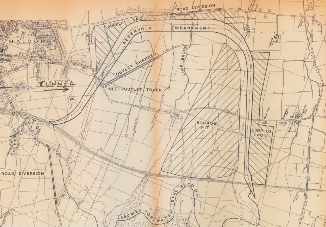
The reservoir on the south side of Maldon would be served by an 8ft 6in diameter tunnel 2.1 miles long from Langford. The Reservoir would have caused the A141 to have been diverted as well as Fambridge Road
Proposed Barrage on the Blackwater Estuary
An alternative scheme was to construct a barrage across the tidal river Blackwater, and analysis was carried out to determine the leaching rate of salt from the estuarine mud.
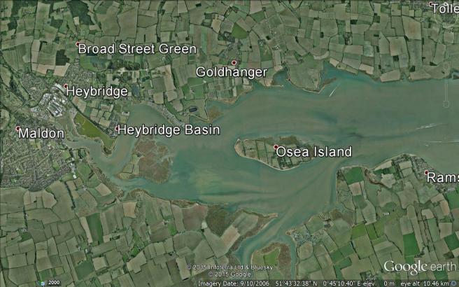
Proposed site of Estuary Barrage on right of Osea Island
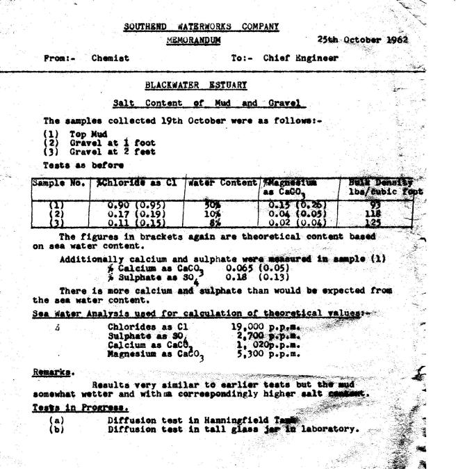
Analysis of Estuarine Mud
Neither of these schemes came to fruition as the Ely Ouse Transfer was preferred by outside bodies ie Environment Authority, as serving a wider area.
Museum of Power ( see 42 Museum of Power )
Following the scrapping of two of the steam pumps, a preservation order was put on the remaining pump and the Pumping station. After several years of disuse it was taken turned into the very popular Museum of Power containing various mechanical pumps and engines. There is also a small gauge railway running around the grounds A new steam boiler was installed allowing the remaining pump to be steam driven as opposed to compressed air.

Southend Water Company, new Treated Water Pumping station 1971
In April 1970 along with a new Treatment works, a new electric pumping station was brought into use, containing three pumps, and the ability to add a further two, if the Treatment capacity was raised from 12 to 24 million gallons per day. This increase was envisaged along with a large Storage reservoir in the Mundon Valley or Blackwater Estuary by creating a barrage. To enable the extra volume of water to be pumped into supply, the 28 inch main was duplicated with a 32 inch main, a break tank reservoir built on Bushey Hill reducing the pumping head by approx. 25 ft . The water then gravitated down the hill to a booster station at Hullbridge, where the initial electric pumps from Langford were installed, to increase the flow though to Oakwood.
Two further reservoirs were built at Oakwood, increasing the storage capacity to 17 million gallons. A burst on the main between Rayleigh and Oakwood resulted in a loss of 2 million gallons before it could be shut off, flooding numerous homes.
However this increase in output at Langford did not occur as the Ely Ouse scheme was approved, and the expansion was carried out at Hanningfield instead of Langford.
Ely – Ouse Transfer.
Also during 1971 saw the start of the Ely Ouse transfer scheme. Water from the Great Ouse was abstracted at Denver sluice and via Channel and pipeline transferred to the Rivers Stour and River Blackwater. To augment low summer river flows.

Langford Water Treatment and Purification
The Clarke’s or Excess lime method for purifying water, had been in use from 1860 in Canterbury, and 1888 in Southampton, and was widely referenced in reference books on Water Treatment. Following laboratory trials an experimental Excess Lime softening and purification plant of 25,000 gallons per day, was built in 1923 at Langford, under the control of Dr’s John C Thresh, and J F Beale, to evaluate its effectiveness on the water from the Rivers Blackwater and Chelmer, which ran for nine months. Following the evaluation of the trials, the full scale plant was built capable of treating 8 million gallons per day, but commencing on 5 million gallons, in 1927.
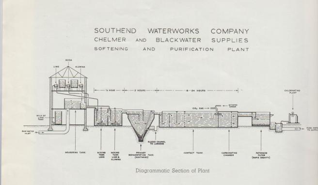
Schematic of Treatment Process
Langford Treatment Plant, with Lime recovery plant on left, the Treated Water balancing reservoir in foreground maintaining an even flow to the pumping station.
River water stored in the Sedimentation reservoirs, was subject to Phytoplankton (Algal) proliferation (blooms) usually followed by large increases in the numbers of Zooplankton species especially Cyclops. Some of the algal blooms imparted Tastes and Odours to the water, that were initially removed by dosing powdered activated carbon prior to filtration. Currently these are removed along with pesticides and herbicides by ozonation and filtration through activated carbon filter beds.The Cyclops penetrated the plant by the passage of their eggs and nauplii through the filters. These were dealt with by Terminal Chlorination killing them in the distribution system prior to them reaching the consumers.The original draw off points from the Reservoirs was at the bottom, but in 1931 additional draw off points were added at half depth, in the event of the bottom water becoming stagnant and devoid of oxygen. Some algal blooms were treated by the use of copper sulphate in sacks being towed around the reservoir by boat.
The treatment process consisted of adding lime, soda ash, and sodium aluminate as a coagulant, to the water in mixing tanks, where the resultant chemical reaction produced insoluble chalk. The soda ash was required periodically to reduce the total hardness to 150mg/lt as CaCO3 as required under the Act. The water then passed to conical shaped sedimentation tanks, entering a a few feet from the top, the insoluble chalk dropped to the bottom of the tank and was removed at intervals. The clarified water collected in channels at the top of the tanks.
Chemical mixing tanks on left, settlement tanks on right, and lime recovery plant to rear
The water then flowed around a series of large contact tanks, taking 18 hours to flow through at maximum flow, to give time for sterilisation.
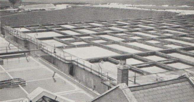
Contact Tanks giving 24 hrs Excess Lime contact
This was followed by pH reduction using carbon dioxide gas, rapid sand filtration and final chlorination. In the early years the final chlorination was intermittent as the water was adequately sterilized by the excess lime. Continuous final chlorination was adopted in June 1940 to comply with war time regulations and continued after the war, to kill the Cyclops and Nais worms that penetrated the plant.

Langford Rapid Gravity Filters
Lime Recovery Plant
A lime recovery plant was also built, and started in the September of 1929 . This recycled the chalk produced from the lime and soda during the softening process. The chalk sludge drained from the settling tanks at intervals was stored in lagoons adjacent to the Lime Kiln. It was then made into a slurry of uniform density 20 – 25 % by weight prior to passing to a continuous rotary vacuum filter which produced a filter cake of 50% by weight, then fed to the kiln.through the kiln. It was a coal fired tubular rotating kiln, 6 ft diameter and 86 ft long , which burnt the chalk back to quicklime CaO, at a temperature of 1,200 – 1,300, and water. Initially the Quicklime was carted to the Treatment works, where it was slaked in mills, producing large quantities of dust and steam in the Chemical House. This was superceeded by large slaker at the Lime Recovery plant, designed by the Resident Engineer Mr Goulding and the slaked lime cream was pumped to the treatment works, eliminating the dust and steam. The lime dust emanating from the chimney in summer , often turning all the local trees white. The Kiln was very efficient converting 99% of chalk. As more quicklime was produced than required, sales were made to local organisations. Quick lime bought in contained 90-92% of available calcium oxide. This fell to about 60% after being reclaimed about 12 times or two years and new lime was bought in. As the contaminated chalk sludge became a problem, in 1945 a Committee on the Reclamation of Water Softening Sludge was set up by the British Waterworks Assn in which the Company played an active part.
Various treatment problems were not identified at the Experimental Plant, one of which was the unstable nature of the water after pH reduction. The resulting chalk deposited on the sand filters, with each grain of sand growing in size until filtration became inefficient, and the sand replaced. An experiment in 1943 to establish if Calgon, dosed prior to the filters, would prevent this, was a failure. With the sand forming large blocks, and fissures through the bed allowing unfiltered water to pass through. After research, a sulphuric acid dosing plant was installed which remedied this problem removing the need to replace the sand.
In the early 1960’s, at a similar time to the pumps being electrified and the output increased, an addition was made to the treatment capacity by the construction of an Accelator. This utilised the Accentrifloc process, whereby lime dosing, mixing, flocculation and sludge removal were all performed in one circular tank. These were also constructed in the first phase of the Hanningfield Works, (see Page30)
Also in the cold winters of early 1960’s, the phenomenon of the chalk being produced in two forms, a light flocculant and heavy crystalline form was investigated. This had previously been experience d in the operation of the lime kiln and blocking of the sedimentation softening tanks. It was discovered that at temperatures below 12 degrees C and in the presence of dissolved aluminium from the coagulant, Calcium Carbonate, Hexahydrate CaCO3.6H2O was formed, containing 6 molecules of water thereby doubling the weight of the chalk molecules. This blocked the sedimentation tanks and the pencil shaped crystals damaged the rubber interiors of the sludge removal pumps. As a result of these findings, the coagulant was changed to ferrous sulphate, an iron compound, and reported by Jack Slack in the SWTE journal 1963 Vol 12.

New Langford Treatment Plant under construction 1970
In 1970, a new treatment plant, of 12 million gallons a day capacity, was built alongside the sedimentation reservoirs, with chlorination as its main sterilising method, eliminating the 24 hour contact time required for excess lime. With no lime Kiln, the chalk produced was then pumped to a gravel pit in Ulting instead of being re cycled. The design of the sedimentation tanks was also modified to produce vertical flow tanks the water entering close to the bottom and producing a suspended chalk blanket for more efficient removal.

This was a far more compact plant, but requiring bulk storage of liquid chlorine amounting to some 50 tonnes. Local inhabitants were all issued with instructions as to the action to take on hearing the Alarm siren, indicating a chlorine leakage. Chlorine gas was that used during the war as it is toxic, heavier than air, and rolls along the ground killing those in the trenches. Fortunately no such incidents took place in Langford.
Also in the early 1970’s water was received from the Ely Ouse Scheme, described later.
Permission was obtained for part of the redundant plant, the Accelator, being used for research purposes on the re use of sewage effluent, results were reported in the SWTE Journal 1972 Vol 21, it was then demolished and the site sold to create Oval Park a company producing state of the art micro chips.
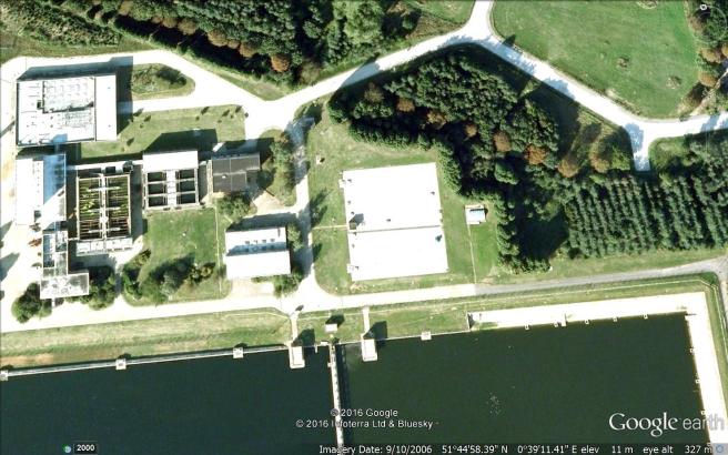
1972 Completed Langford Treatment Plant, with two new raw water pumping stations on the bank of the reservoirs.
In 1982, the Company requested a relaxation of the hardness limit and an act, The Essex Water Order 1983, was passed allowing the Water Company to raise the hardness level to 300 mg/lt from the 1st February 1984. This resulted in no soda ash used in the treatment, reducing the sodium content, thereby eliminating the Zinc corrosion, and potential health effects of high sodium levels.
Also resulting in a reduction in treatment costs, and reduction of the amount of chalk produced. The Act requiring the water supplied from the Hanningfield and Langford works, to be below 300mg/l is still in force, and limits when the supply from Langham/Layer can be used.
Various other treatment adaptions were made such as the addition of poly electrolyte to aid sedimentation, and change from Aluminium to Iron as a coagulant. Iron was preferred because it removed phosphate.
A research project was conducted with the London Hospital regarding Aluminium levels in the brain and Dementia.
Pesticide Removal Unit top left of picture. Note the green Algal bloom in right hand reservoir.

The Liquid Oxygen storage tank, to feed the Ozone generators for pesticide removal. Situated in front of the De Nitrification plant.
In 1996, as requirements for the removal of pesticides and herbicides in drinking water were becoming more stringent, additions were made to the treatment including, pre treatment with ozone gas, which broke up the long chain molecules, and filtration through activated carbon filters. This reduced the amount of Chlorine required, and the bulk storage of 50 Tonnes was replaced in 2014, with a drum store containing 1 tonne drums from which the chlorine was dosed. It also allowed the development of houses in the vicinity of the plant, which had been refused when the bulk store was operational.Unfortunately this does not remove Metaldehyde commonly found in Slug pellets, and the chemicals found in pet flea treatment, both an increasing problem. The Ozone generators were constructed in Zurich and I along with company engineers visited the manufacturing plant to ensure their safe working, prior to shipping to Essex
Effluent Recycling plant top left of picture. Note shadow of tall oxygen tank on right
River Pollution
River Pollution can be either Environmental or Industrial.
Industrial Pollution
Nitrate pollution
Run off from agricultural land can be a problem, caused by animal waste being spread on the land, and fertilisers being sprayed on the crops, especially those high requiring high Nitrate levels such as oil seed Rape Nitrate is not easily removed from large volumes of water, and river abstraction ceases when nitrate levels exceed the European Directive level. This is normally an autumnal problem until all of the nitrate has been washed from the soil. In summer nitrate can be biologically removed by plants in the river and large storage reservoirs such as Hanningfield, where dilution also takes place in these making cessation of abstraction less important.
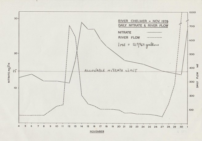
(DNW Chart)
Correlation between river flow and Nitrate concentration
Pesticide/ Herbicide Pollution
During the 1970’s problems were reported by commercial Tomato growers, that malformed tomatoes were being produced. After some research it was determined that a Chemical, 2,3,6, Trichlorobenzoic Acid was present in the water transferred from the Ely Ouse system, which was responsible.
Algal Pollution
Apart from the usual river pollution by sewage and high autumnal nitrate levels, there was also substantial algal blooms in the storage reservoirs, which fuelled by increased sunlight, fed off the nitrate and phosphate, and ironically chlorine added at Langford. As the smaller of these algae penetrated the rapid gravity filters at both Langford, measures were required to reduce these algal “blooms”
Initially at Langford, the sedimentation reservoirs were dosed with copper sulphate, prior to the later extension of the treatment plant to include ozonisation and activated carbon filtration. The ozone broke up the long chain molecules which were the product of the algal blooms and which imparted a taste to the water. The activated carbon then absorbed the resultant smaller molecules.
