For any comments or queries regarding this page
Please contact David N Williams on pondside@talktalk.net
Early water supply systems built by the Romans had no storage facilities, water ran continually from its source, via stone channels and lead pipes to provide first drinking fountains, followed by baths, and finally to flush communal toilets. Wealthy Romans had an individual supply which was measured into the house through a lead pipe of known diameter. They were charged upon the diameter of the lead pipe, with the water flowing continually, although after a while plug cocks were made and inserted into the pipeline to stop the flow, In other countries channels or early pipes made from tree trunks, and even lead were used to distribute water to a few houses. These often fed fountains or conduits for people to collect water from, and enterprising people set up as water carriers distributing water from these to houses for a small sum.

The Famous Roman Trevi Fountain DNW Photo
The next development was underground storage tanks or cisterns. With the invention of pumps, pumping water from ever deeper wells, eventually water was pumped up into water towers to supply an ever growing population.
It is this pressure and diameter of the supply pipes that determine the flow from taps. The pressure is determined by the height of the water tower or reservoir above the premises supplied. At the present time, once water has been approved for consumption it required to be stored in covered reservoirs or towers to prevent contamination. These Reservoirs and Towers also provide water at times of peak demand such as early morning and early evening.
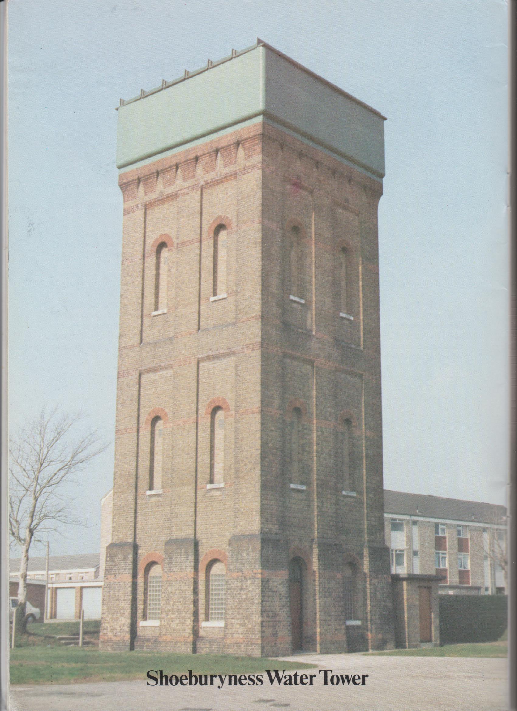

Left Shoeburyness old Style tower with metal tank on Brick building Right Oxley Green Tower reinforced concrete with an integral tank

Engineer John Wren (on right) on top of Shoeburyness Tower
In 1895 the Shoeburyness District became Urban and Received a local Authority Loan of £8500 . £3000 to purchase land, sink a deep well, and £5,500 to build a water Tower, 50 ft high, and gas pumping engines and water mains.The well being 475 ft deep and yielding 5000 gallons per hour. This was completed in 1897, and the supply was laid on to all of the houses apart from the outlying ones. The tank on the water tower holding 43,000 gallons. A well had also been bored at The Garrison to a depth of 1,300 feet in 1889.

The modernised Shoeburyness Tower enlarged and now Flats

Maldon Treated Water Reservoir
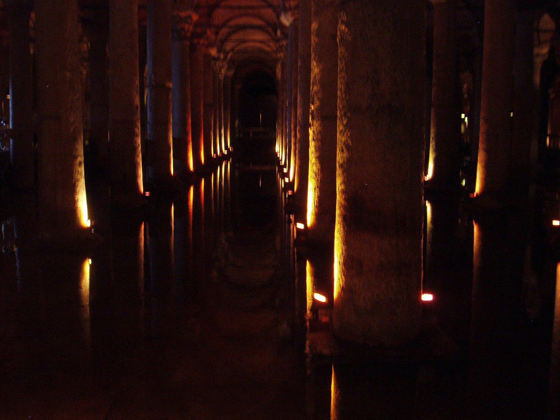
Disused Cistern(Reservoir) in Istanbul, where musical events are held. Decorated base of column below in the same reservoir. There are also small fish now resident DNW


Interior of disused Reservoir in Budapest

This Reservoir, the largest of its time, was constructed in 1874 , to supply southern Paris, from Springs 100 miles away
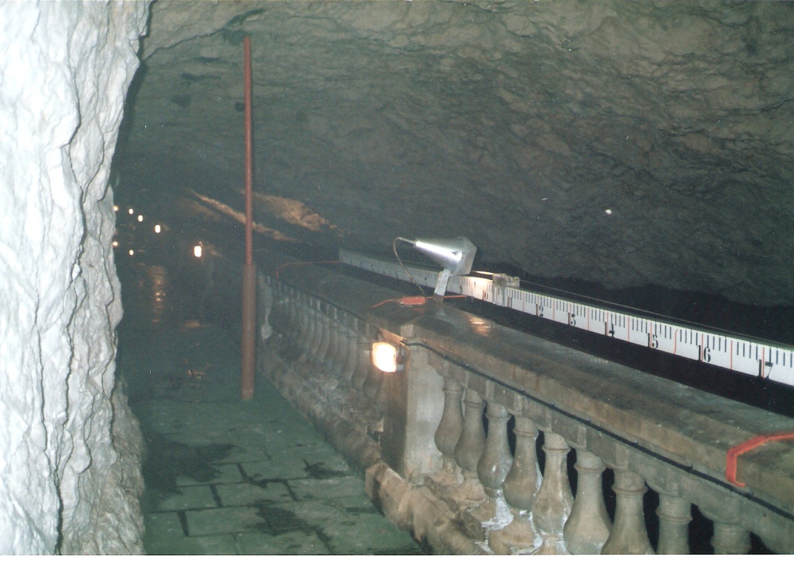
Interior of one of eleven reservoirs, inside the Rock of Gibraltar DNW Photo

Built in 1898, the Vange Reservoir, near Basildon, was the first of the Southend Company’s covered reservoirs

Vange Reservoir under construction 1912
Water Mains
Early water mains were made of hollowed out elm trunks, clay pipes and lead pipes. Following these water mains were constructed in a variety of materials.
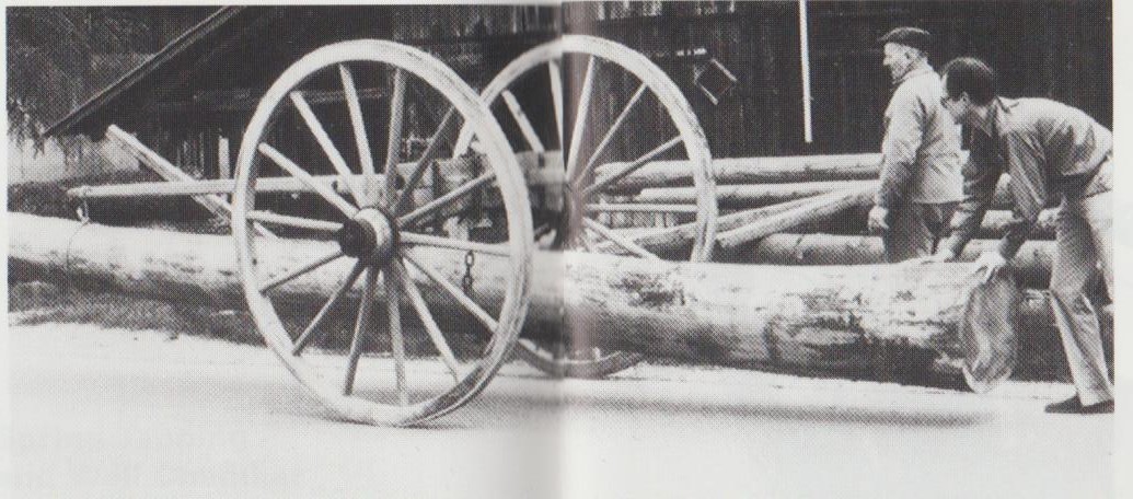
Tree Trunk being prepared for Boring Machine

Hand Boring tree trunks

Water powered boring machine
Cast iron was most commonly used as being strong and durable and made in sizes commonly ranging from 3 inches to 52 inches. It was prone to external corrosion when laid in clays with high sulphate content, by sulphate reducing bacteria. Also internal corrosion from some waters, containing high oxygen levels.

Laying Cast Iron Main

Repairing Cast Iron Main Southend on Sea 1950
Concrete Asbestos mains were introduced to overcome the corrosion of cast iron. However these are prone to ring fractures when lain in clay which expands and contracts substantially according to water content.
Steel mains were also used which had to be welded together for strength.
Fibreglass mains were found to be unsuitable due to the gel coat promoting biological growths of moulds and fungi from spores carried in the water, unaffected by the treatment processes. Medium density polyethylene is now widely used as the current material of choice, being resistant to fracturing and corrosion. It can be manufactured up to 24 inches diameter.

Welding Steel Main
Continuity of Supply
As the demand for water varies substantially over 24 hours, and treatment plants operate at a constant flow, storage reservoirs and towers have to be utilised to provide for the variation. Generally the bulk of the water stored is in underground concrete reservoirs, with water tight roofs and hatches to maintain the purity of the treated water. These are usually situated on high ground, but in some cases concrete towers are built to add pressure to the system, water being pumped up into them.
In 1901, the Southend distribution system comprised of a water Tower holding 50,000 gallons and an enclosed brick arched Reservoir holding 300,000 gallons receiving water from 5 wells.
In 1948 the Southend distribution system comprised of nine service reservoirs, Five towers and five booster stations. Together with 590 ninety miles of trunk and service mains, varying from 30 in downwards. By 1967 with the addition of the Hanningfield Works this had increased to 1022 miles of mains.
On one occasion, one half of the storage reservoir supplying Witham was emptied for inspection, and the high ground water level around the reservoir, fractured the concrete base and filled the reservoir with ground water.
Early small supply pipes between the houses and water mains were made of iron and lead. Iron was prone to rust when the water had a high oxygen content. Where lead pipes are still in use, phosphate is often dosed to coat the pipe and prevent lead leaching into the supply. These were followed universally by copper pipes.
Currently Medium Density PolyEthylene (MDPE) plastic pipes are used which do not rust or contaminate the water. The smaller sizes can be compressed to stop water flow in the event of a leak downstream.
Leak Detection
Distribution mains are divided into zones which can be isolated with valves, apart from one feeder main which has installed a waste detection meter. This accurately records the flow over 24 hours, to detect ant abnormal high flows at night which can then be investigated.

Modern leak detection using microphones is now employed, to pinpoint leaks where the water is escaping.

